We mainly consider the insulation resistance tester in the low-voltage test, and whether it will break down in the high-voltage test. The resistance is extremely low during the breakdown, and it almost becomes a conductor. The insulation resistance test is a qualitative test that gives an indication of the relative quality of an insulation system. The test is usually performed with a DC voltage of 500V or 1000V and the result is expressed in megohm resistance. The hipot tester also applies high voltage to the object under test, but the applied voltage is higher than that of the insulation resistance test, and can be performed under AC or DC voltage, and the result is expressed in milliamps or microamps. In some specifications, the insulation resistance test is performed first, followed by the withstand voltage test. If a DUT fails the insulation resistance test, then the withstand voltage test, which is usually performed at higher voltages, will also fail.
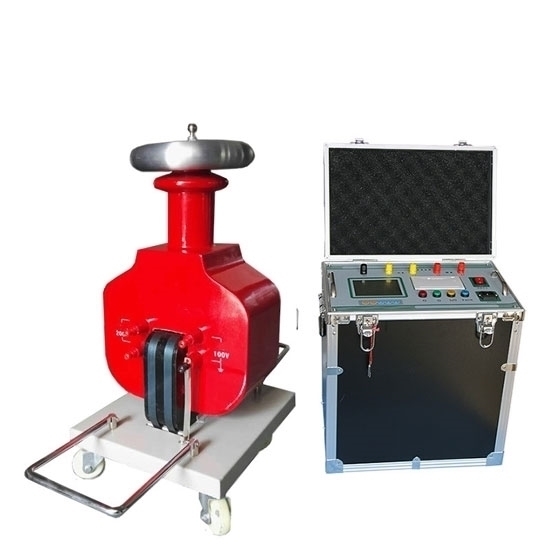
Hipot Tester
The hipot tester is also called an electrical dielectric strength tester or a dielectric strength tester. A test of applying a specified AC or DC high voltage between the live part and the non-live part (usually the casing) of the electrical appliance to check the withstand voltage capability of the insulating material of the electrical appliance. In the long-term operation of the electrical appliance, not only the rated working voltage, but also the short-term overvoltage effect that is higher than the rated working voltage caused by the operation process (the overvoltage value may be several times higher than the rated working voltage value) . Under the action of these voltages, the internal structure of the electrical insulating material will change. When the overvoltage intensity reaches a certain value, the insulation of the material will break down, the electrical appliance will not operate normally, and the operator may be electrocuted, endangering personal safety.
Boost section
It is composed of a voltage regulating transformer, a step-up transformer and a power-on and cut-off switch of the step-up part.
The 220V voltage is connected to the step-up transformer by connecting and cutting off the switch to the voltage-regulating transformer. The user can control the output voltage of the step-up transformer simply by adjusting the voltage regulator.
Control section
It consists of current sampling, time circuit and alarm circuit. When the control part receives the start signal, the instrument immediately turns on the power supply of the booster part. When the current of the circuit under test exceeds the set value and an audible and visual alarm is issued, the power supply of the booster circuit is cut off immediately. Cut off the boost circuit power supply when receiving reset or time out signal.
Display circuit
The display shows the step-up transformer output voltage value. Display the current value and time from the current sampling part. The time value of the circuit is generally a countdown.
The above is the structure of the traditional hipottester. With the rapid development of electronic technology and single-chip, computer technology; the program-controlled withstand voltage tester has also developed rapidly in recent years. The main difference between the program-controlled hipot tester and the traditional hipot tester is the boosting part. The high-voltage boost of the program-controlled withstand voltage instrument is not adjusted by the voltage regulator through the mains, but is controlled by a single-chip computer to generate a 50Hz or 60Hz sine wave signal and then amplify and boost through the power amplifier circuit, and the output voltage value is also determined by the single-chip computer. It is controlled by a chip computer, and other parts of the principle are not much different from the traditional pressure tester.
Insulation Resistance Tester
The insulation performance of electrical products is one of the important signs to evaluate the quality of their insulation, which is reflected by the insulation resistance.
We measure the insulation resistance of the product, which refers to the insulation resistance between the live part and the exposed non-live metal part (casing). According to different products, apply DC high voltage, such as 100V, 250V, 500V, 1000V, etc., and specify a minimum Insulation resistance value. Some standards stipulate that the insulation resistance is not less than 1MΩ per kV voltage. At present, in the product standard of household electrical appliances, only the thermal insulation resistance is usually specified, and the insulation resistance value under normal conditions is not specified.
The insulation resistance value under normal conditions is formulated by the enterprise standards. If the normal insulation resistance value is low, there may be some hidden danger or damage in the insulation structure. If the insulation resistance of the motor winding to the casing is low, it may be caused by damage to the insulation of the winding’s equalizing slot when the wire is embedded. When using electrical appliances, due to sudden power-on or power-off or other reasons, the circuit will generate overvoltage, which will cause breakdown at the damaged insulation, causing personal safety or threat.
The structure and composition of insulation resistance meter
Insulation resistance meters are also called megohmmeters, shake meters, and meg meters. The insulation resistance meter mainly consists of three parts. The first is a DC high voltage generator, which is used to generate a DC high voltage. The second is the measurement loop. The third is display.
DC high voltage generator
To measure the insulation resistance, a high voltage must be applied at the measuring end. The high voltage value is specified in the national standard of the insulation resistance meter as 50V, 100V, 250V, 500V, 1000V, 2500V, and 5000V. There are generally three methods to generate DC high voltage. The first hand-cranked generator type. At present, about 80% of the megohmmeters produced in my country adopt this method (the source of the name of the shaker). The second is to boost the voltage through the mains transformer and rectify it to obtain a DC high voltage. The method used by the general mains type megohmmeter. The third is to use transistor oscillation type or special pulse width modulation circuit to generate DC high voltage, which is generally adopted by battery type and mains type insulation resistance meters.
Measurement loop
In the shaking table (megger) mentioned above, the measurement circuit and the display part are combined into one. It is completed by a flow ratio meter head, which consists of two coils with an included angle of 60° (about 60°), one of which is connected to both ends of the voltage, and the other is connected to the measurement loop. middle. The deflection angle of the pointer of the meter head is determined by the current ratio in the two coils. Different deflection angles represent different resistance values. The smaller the measured resistance value, the greater the coil current in the measurement loop, and the greater the deflection angle of the pointer. .
Another method is to use a linear ammeter for measurement and display. Because the magnetic field in the coil is non-uniform in the current ratio meter head used above, when the pointer is at infinity, the current coil is just at the place where the magnetic flux density is the strongest, so even though the measured resistance is very large, the current coil flows through it. The current is very small, and the deflection angle of the coil will be larger at this time. When the measured resistance is small or 0, the current flowing through the current coil is large, the coil has been deflected to a place where the magnetic flux density is small, and the deflection angle caused by this will not be very large. In this way, nonlinear correction is achieved. Generally, the resistance value display of the head of the megohmmeter needs to span several orders of magnitude.
However, when the linear ammeter head is directly connected in series to the measurement loop, it will not work. At high resistance, the scales are all crowded together and cannot be distinguished. In order to achieve nonlinear correction, nonlinear components must be added to the measurement loop. So as to achieve a shunt effect when the resistance value is small. There is no shunt at high resistance, so that the resistance value display reaches several orders of magnitude. With the development of electronic technology and computer technology, digital display meter gradually replaces pointer meter. The digital measurement technology of insulation resistance has also been developed, among which the voltage ratio meter circuit is one of the better measurement circuits. The voltage ratio meter circuit is composed of a voltage bridge circuit and a measurement bridge circuit. The signals output by these two bridges are converted into digital values and displayed directly through A/D conversion and then processed by a single-chip microcomputer.
Selection of insulation resistance meter and hipot tester
The choice of insulation resistance meter is mainly to measure the voltage value, and the other is to measure the range to be measured, whether it can meet the needs. If the measurement is very frequent, it is better to choose the alarm setting function.
The most important thing in choosing a hipot tester is two indicators, the maximum output voltage value and the maximum alarm current value must be greater than the voltage value and alarm current value you need. Generally, the test product standard specifies the applied high voltage value and the alarm judgment current value. If the applied voltage is higher and the alarm judgment current is larger, then the power of the step-up transformer of the withstand voltage instrument is required to be greater. Generally, the power of the step-up transformer of the withstand voltage instrument is 0.2kVA, 0.5kVA, 1kVA, 2kVA, 3kVA, etc. The highest voltage can reach tens of thousands of volts. The maximum alarm current is 500mA-1000mA, etc. Therefore, you must pay attention to these two indicators when choosing a withstand voltage meter. If the power is too large, it will cause waste, and if the power is too small, the withstand voltage test cannot correctly judge whether it is qualified or not.
According to IEC414 or (GB6738-86), the power method of selecting the hipot meter is considered to be more scientific. ” First adjust the output voltage of the withstand voltage tester to 50% of the specified value, and then connect the test object. When the observed voltage drop is less than 10% of the voltage value, the power of the hipot tester is considered sufficient. “That is, if the voltage value of the withstand voltage test of a certain product is 3000 volts, first adjust the output voltage of the hipot tester to 1500 volts and then connect the test object. 150 volts, then the power of the withstand voltage meter is sufficient. There is a distributed capacitance between the live part of the test object and the casing.
The capacitor has a capacitive reactance, and when an AC voltage is applied across the CX capacitor, a current will be induced.
The magnitude of this current is proportional to the capacity of the CX capacitor and the value of the applied voltage. When the current reaches or exceeds the maximum output current of the withstand voltage tester, the test withstand voltage tester cannot correctly judge whether the test is qualified or not.