The test system has three modules: program-controlled power module, signal acquisition and conditioning module and computer control system.
It is composed of a program-controlled power supply with an output position of 0V~140V and a high-voltage transformer. Under the control of the microcontroller ADCm842, the output voltage of the program-controlled power supply can be boosted by the transformer to obtain the set output voltage value.
Module design
In the actual hipot tester equipment, different test voltages may be required to be applied to different products, which requires the output test voltage of the withstand voltage test system to be adjustable. PWM (Pulse Width Modulation) is one of the main methods to control the inverter power supply to achieve adjustable voltage output. The theoretical basis of PWM control is based on an important conclusion of sampling control theory, that is, when narrow pulses with equal impulses and different shapes are added to the links with inertia, their effects are basically the same. T
he SPWM waveform is to replace the sine wave with pulses of equal amplitude and unequal width. The midpoint of the pulse coincides with the midpoint of the sine equally divided, and is equal to the corresponding sine area, and the width of each pulse changes according to the sine law. There are many ways to generate the SPWM wave, which can be generated by a dedicated integrated chip or a combination of general-purpose circuits, or by a single-chip microcomputer. The system uses the single chip ATMEGA16L to generate SPWM wave, and uses the internal accumulator and comparator of the single chip ATMEGA16L to output the SPWM wave on the PC4 port by adjusting the duty ratio.
The program-controlled voltage source adopts one-way 220V power frequency AC power to obtain DC voltage through bridge rectification and provides stable DC power for the inverter circuit after filtering. At the same time, the single-phase SPWM wave generated by the single-chip microcomputer passes through the non-gate to generate an SPWM wave that is complementary to the output phase of the single-chip microcomputer. The trigger pulse train can be controlled on and off. Finally, the output of the inverter bridge composed of IGBTs can be low-pass filtered to obtain a standard sine wave, and the amplitude of the sine voltage is adjustable from 0V to 140V.
Signal acquisition and conditioning module
The information acquisition and conditioning module have a sensor, a signal conditioning circuit, and an overcurrent protection circuit, and the leakage current of the test loop enters the signal acquisition and conditioning circuit through the sensor. In the signal acquisition and conditioning circuit, the leakage current signal is I/V converted into a voltage signal that meets the A/D input range. The overcurrent protection circuit is activated when the test product or circuit fails.
Module design
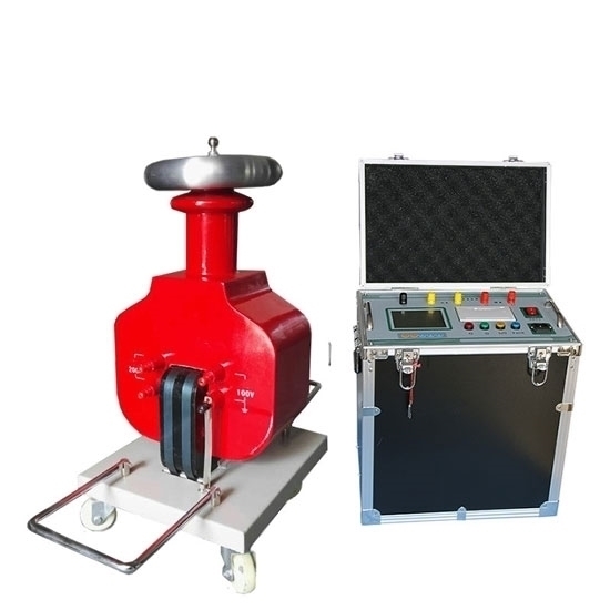
The parameters that need to be monitored in the withstand voltage test are the value of the transformer output high voltage and the leakage current value of the test circuit. The secondary winding of the booster transformer used in the test system has two voltage outputs of 0~5000V and 0~5V. When the high voltage output of the secondary winding changes from 0V to 5000V, the low voltage output of the secondary winding of the transformer changes from 0V to 5V, and there is a good linear relationship between the two outputs. The test starts within the set boost time interval. The voltage output from the low-voltage side of the secondary winding of the transformer enters the single-chip ADCm842 after the isolation transformer and the signal conditioning circuit.
The 12-bit ADC in the single-chip ADCm842 converts at a high speed of 420,000 times per second. A/D conversion, the digital quantity after A/D conversion is sent to the computer and compared with the set value of the computer until the output voltage meets the set voltage value, we consider that the actual output test voltage meets the requirements of our set value.
The test range of the leakage current of the withstand voltage test system is 0mA ~ 20mA. At the beginning of the test, the leakage current of the device under test passes through the current transformer, and then the sampled current is converted into a voltage by the I/V conversion circuit, and the corresponding A/D is carried out in the microcontroller. After conversion and calculation, the leakage current value of the device under test under the set voltage condition is finally obtained.
By comparing it with the leakage current value specified in the safety standard, it can be checked whether the withstand voltage test of the device is qualified. In the actual test, an overcurrent protection circuit is designed on the secondary side of the current transformer. When an overcurrent condition occurs, such as the device under test is broken down or the insulation of the device under test is defective, the power supply is quickly cut off, and the test is terminated to protect the test system is not damaged.
The conventional signal conditioning part adopts the analog operation of true RMS, and the RMS and peak value operation of the leakage current signal are input to the single-chip computer or computer after the hardware circuit is completed. This method of signal conditioning ultimately only obtains the peak or RMS value of the leakage current signal. This method not only has low precision, but also loses frequency information, and cannot truly reproduce the actual waveform of the leakage current.
The system adopts high-speed A/D conversion to directly collect the AC voltage value into the computer, calculates the peak value and effective value according to the user’s requirements, and draws the real-time leakage current waveform so that the user can monitor the leakage current situation intuitively. The computer can also perform software correction to remove errors caused by drift and offset. According to the actual situation, digital filtering can also be used to remove high-frequency interference. This signal conditioning method simplifies the hardware circuit, has low cost, high test accuracy, and good test stability. Due to the high test voltage of the withstand voltage test, to ensure the safety of the test, hipot tester is necessary to ensure that the casing of the test system is well grounded during the test.
Computer control system
The single-chip ADCm842 and the computer constitute the PC control system, which controls the voltage rise and fall, A/D conversion, data processing, and analysis during the test process.